We were switching a line from 7,200v to 14,400v when it happened. After we gathered at the rendezvous point, a lineman energized the line. BOOM! A fuse blew down the road. Well, naturally we all turned toward the boom, trying to figure out where it was and what had gone wrong, and a two-man crew jumped in their truck and headed out. Not five minutes later, “We found it,” came over the radio. So here we all go toward the source of trouble.
Raising line voltage is a labor intensive thing. You make sure all the insulators are rated for the new voltage; you have to make sure the reclosers can handle the voltage as well. You replace all single voltage transformers with duel voltage. All fuses are changed the day of the cut-over. Then you get every bucket truck and every lineman with climbing hooks and someone to drive them to switch the transformers from 7,200v primary to 14,400v primary, otherwise a customer could find their 240v service was now 480v. Not a good thing. This couldn’t be done from the ground, so everyone was out changing transformer primary voltage and replacing the fuses while they were at it.
You also have to change out the lightning arresters, and that was the “gotcha” that day. A lightning arrester rated for the old voltage somehow wasn’t changed out. When the lineman energized the line, the lightning arrester operated, creating a fault that blew the fuse.
While spark-gap arresters are still used on the electric grid, mostly as fall-back, metal oxide arresters are the norm. These are like big versions of the Metal Oxide Varisters used in small surge suppressors. Instead of being little disks, they are long insulator encased things, but they operate the same way. Normally a MOV acts as an insulator until voltage climbs to a certain level, then resistance drops and allows current to flow. In arresters and MOV surge suppressors, this over-voltage is shunted to ground, hopefully protecting equipment.
MO lightning arresters are fast – and they, and spark gaps, both on the line and the gas-tube spark gap arresters used on communication lines – are all that I’ve known. When asked the history of lightning arresters, all I knew was what was on the lines 30+ years ago through now. What was used on telegraph lines in 1859 was a mystery. Did they even have lightning arresters at the time of the Carrington Event?
It turns out they did. A good source of information can be found here at ArresterWorks. Another, on 19th Century telegraphs, is Ask the Wire Chief. The first seems to be a simple spark gap made of wire and brought within half an inch of the telegraph line. Spark gap arresters at telegraph stations were in use in 1859 in the form of a bar a short distance from the galvanized iron wire used as a conductor (overhead telephone lines would use a similar steel conductor well into the 20th Century). Incoming wires had a stand-off before running into the building, in case lightning did hit, and the wall was usually sheeted in tin in case the telegraph console caught fire from lightning.
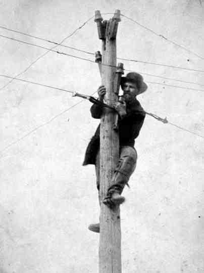
That, along with lightning rods fashioned from wire and attached to the poles, seems to have been about it. Neither is apparent in the pole in the photo above, taken in 1862 or 1863.
A lightning rod wouldn’t have helped in the Carrington Event, where Geomagnetic Induced Current (GIC) flowed along every conductor. All that stood between telegraph stations and damage was spark gap arresters.
Just how well the arrester worked would depend on a lot of things, from how far it was from the wires to how well it was maintained. Discharging lightning can leave spark gap arresters pitted, which means the bar would have to be cleaned up with a file every now and then.
There were different lightning arrester schemes tried over the years, but for the power industry the largest advance seems to have been the electrolytic lightning arrester early in the 20th Century. All lightning arresters work by having high resistance that serves as an insulator. In the case of a spark gap arrester, that’s air. In an electrolytic lightning arrester, it was oxidixed aluminum plates in an electrolyte. Designs with oxidized pellets came later (and here I seem to remember coming across a similar scheme for communications, but can’t recall the time frame). Each was a marked improvement in operation and cost, and ultimately we ended up with the MO arresters used today.
So, just when does a lightning arrester kick in? Calculations for voltage rating are based on phase-to-phase, also called line-to-line, voltage. That 7,200 volt line I mentioned would be called a 12.5 KV line because 7,200 phase to ground x √3 = 12,471 volts (that has to do with the 120° separation of the AC cycle of three-phase – I find it easier to understand using phasor diagrams, but that’s another topic). The 14,400v line would be called a 25 KV line for the same reason. It also varies by the condition of the grounds. If everything is up to snuff, the recommended point for a lightning arrester rated at 12.5 KV to kick in would be 15 KV, and 30 KV for a 25 KV lightning arrester.
What about the spark gap? I was afraid you were going to ask that. Joseph Henry, who came up with the idea of a pole spark gap arrester made of wire, recommended a half inch gap. That might be around 40,000 volts, depending on the characteristics of an arc-over to wire, and assuming everything is properly maintained. The break-down voltage, the voltage when the arc forms, varies depending on the shapes of the conductors in the spark gap, so I wouldn’t swear to this figure. I might have calculated it wrong, too.
This has interesting implications for the Carrington Event. Either Henry’s suggested spark gap arrester wasn’t used on poles and the equipment wasn’t maintained, or multiple discharges raised the point the gaps arced over, or all the damage happened under that rough figure of 40,000 volts.
Modern lightning arresters operate faster than air gaps, and for the distribution voltages above would open under 40,000 volts. Transmission line arresters are another issue, and would open at higher voltages. That said, the grid operates at voltages much higher than the telegraph lines of 1859. The question is how does the voltage where a lightning arrester kicks in relate to the rated voltage of transformer winding insulation.
The big question, since utilities have lightning protection as well as over-current protection, is how does GIC do a number on transformers? And how to calculate GIC in the first place.
Lightning arresters are just part of the issue. There’s more that I need to look into.
For more reading:
History of Arresters on Power Systems 1790 – 1890
History of Arresters on Power Systems 1890 – 1930
